|
DTM Module
PLAN Module
PROF
& DYNPROF Modules
TMPL Module
GRAD Module
PTS, EDITRI
and TUTIL Modules
XSEC Module
VOL Module
UTIL Module
GCMDRIVE
Module
SPEED Module
CSC1, CSC2
and CSCi Modules
XPAVE Module
GCMTAB Module
PAVE Module
GavranSTL
Module
|
GCM++
Modules
In GCM++ there are two major toolbars, “GAVRAN CLASSIC” and
“GAVRAN NEW”. On Fig1-01, “GAVRAN CLASSIC” is aligned along the left edge of
the screen, while “GAVRAN NEW” is on the right side. Apart from these two
major toolbars, new toolbar “GavranSTL”, positioned below “GAVRAN NEW”, is
added in GCM++.
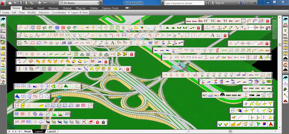
Fig.1-01. GCM++ Toolbars
Each of these three major toolbars further opens new toolbars,
each of them referring to a particular group of commands, or modules:
-
“GAVRAN CLASSIC” contains 11
toolbars, or command groups: DTM, PLAN, PROF, TMPL, GRAD, PTS, EDITRI, TUTIL,
XSEC, VOL and UTIL.
-
“GAVRAN NEW” contains 7 more
toolbars: GCMDRIVE, DYNPROF, CSC1, CSC2, CSCi, GCMTAB and GCMPAVE.
-
“GavranSTL” contains 4 toolbars:
ORIENT, INQUIRE, CORRECT and BUILD.
Back to top
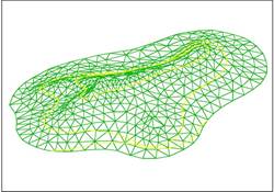
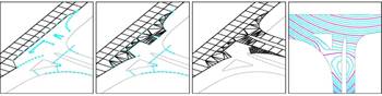
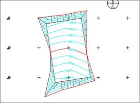
DTM Module
 This group of commands is intended for digital terrain modeling
and the modeling of existing civil engineering facilities. By using these
commands, you can generate both the TIN and grid terrain model, generate
contour lines of existing and proposed surfaces etc. There are also tools for
the analyses of watersheds and drainage patterns, zero-line generation etc. This group of commands is intended for digital terrain modeling
and the modeling of existing civil engineering facilities. By using these
commands, you can generate both the TIN and grid terrain model, generate
contour lines of existing and proposed surfaces etc. There are also tools for
the analyses of watersheds and drainage patterns, zero-line generation etc.
 Triangles representing terrain surfaces, paved areas, graded
areas, retaining walls and other natural and manmade surfaces could be placed
into separate layers. You can quickly generate contours with different
intervals from these separate groups of triangles. Triangles representing terrain surfaces, paved areas, graded
areas, retaining walls and other natural and manmade surfaces could be placed
into separate layers. You can quickly generate contours with different
intervals from these separate groups of triangles.
While working in urban areas, you
can combine TIN models with the models of underground facilities, buildings
and overpasses which could be modelled by using GCM++ tools as well. All
these facilities could be included into extracted cross sections and
profiles.
Back to top
PLAN Module
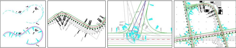
While working in plan projection, most existing software
solutions are tangent based. That is to say, tangents are drawn first and
spiral-arc-spiral shapes are added at the tangent intersections. GCM++
supports both tangent based and floating geometry. When working with floating
geometry, arcs and straight sections are set first. Then, these elements are
slightly rotated around specified points and connected by using clothoids.
If, for example, rotation points coincide with the corners of the nearby
buildings, then you can be sure that, while rotating, no element will come
closer to these buildings. By using floating geometry, you can construct
reverse "S" curves with no straight sections.
When working with tangent based
geometry, full dynamics is at your fingertips. Any change of tangents causes
dynamic changes of spiral-arc-spiral shapes. For example, move some of the
tangents and the entire centerline is modified, together with its offsets,
stations, labels, accompanying files ... Even crossroads behave dynamically.
Left and right turn lanes, traffic isles - everything could be rearranged
automatically. Move one of the centerlines from the network and all elements
and centerlines linked either to this particular centerline or to one of its
offsets are changed automatically (together with their labels, stations,
files etc.).
Back to top
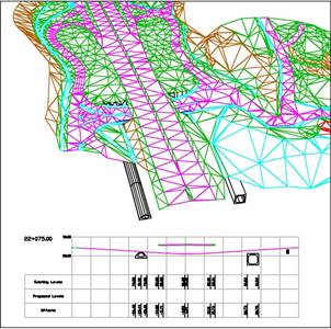
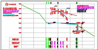
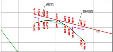
PROF & DYNPROF Modules
 By using these commands, you can literally cut longitudinal
profiles out from the terrain model or from the models of the existing
structures, design vertical alignment, correlate horizontal and vertical
alignment, label profiles etc. While working in dynamic longitudinal
profiles, points of vertical intersections, tangents and vertical curves are
dynamically linked, providing creation of fully dynamic vertical alignments.
By moving some elements of vertical geometry, entire alignments are
recalculated and modified, together with all accompanying labels. By using these commands, you can literally cut longitudinal
profiles out from the terrain model or from the models of the existing
structures, design vertical alignment, correlate horizontal and vertical
alignment, label profiles etc. While working in dynamic longitudinal
profiles, points of vertical intersections, tangents and vertical curves are
dynamically linked, providing creation of fully dynamic vertical alignments.
By moving some elements of vertical geometry, entire alignments are
recalculated and modified, together with all accompanying labels.
Back to top
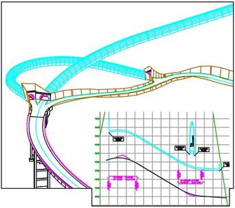
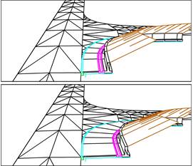
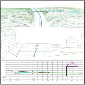
TMPL Module
Cross section’s arrangement and its changes along the centerline
are defined by using, the so called templates. Based on horizontal alignment,
vertical alignment and the templates, triangulated 3D model of a linear
facility (highway, railway) is generated. Anything that can be drawn by using
LINE entities might become a template: road, runway, riverbed, tunnel,
bridge. The templates are attached to the key stations along the centerline,
depicting both the superelevation concept and the arrangement of the road
details.
Until GCM++, there were the two basic types of 3D models: the
static models and the dynamic ones. Static models are complex triangulated
structures, including all the details, such as pavement layers, drain pipes,
curbs etc. Dynamic models are simpler, but they are created from the
dynamically interlinked triangulated networks, thus enabling automatic model
rearrangement whenever the centerline is modified. The dynamic models are
generated from the templates dynamically attached to the key points along the
centerline (or in relation to these key points), maintaining the appropriate
superelevation concept.
GCM++ introduces a new kind of the
dynamic 3D model. This kind of model consists of a two seamlessly linked
models: the model of the pavement and the model of the road details along the
pavement edges. The model of the pavement is generated upon the pavement
blocks dynamically attached to the centreline (the same blocks serving CSC –
Cross Section Constructor techniques introduced in GCM2006), while the road
details come from the “*.csc” files. This type of files is explained in CSC1,
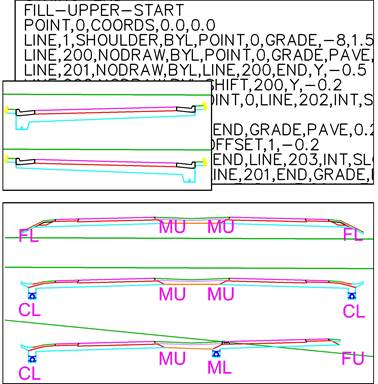
CSC2 and CSCi sections. Basically, CSC details are defined separately for FU,
FL, CU, CL, MU and ML cases. The meaning of these abbreviations is: the first
letter (F or C) tells if the particular pavement edge is on the fill or in cut,
while the second letter tells if the pavement edge is upper or lower edge
(higher or lower than the opposite edge of the pavement). The last two cases,
MU (median upper edge) and ML (median lower edge), refer to the median cases
and are used only on motorways (dual carriageways).
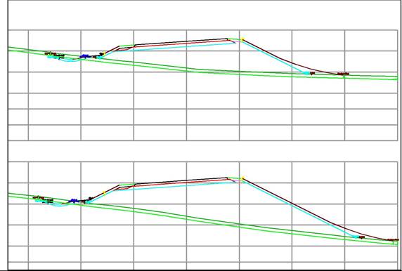
While the pavement model is generated as a dynamic regular
triangulated network, referring to the pavement blocks attached to the
centerline, the road detail models are generated along the pavement edges like
triangulated “accordions”. The “accordion” contains all CSC details (FU, FL,
CU, CL along the outer pavement edges or MU, ML along the median edges).
Imagine that the “accordion” is compressed and when the particular pavement
edge at the specific cross section of the road during the generation of the
model or during the model’s dynamic repositioning comes into the Fill Upper
position, the “accordion” expands into the 3D form matching FU detail. At
some other point, where the pavement edge comes into the Cut Lower position,
the “bellows” of the “accordion” expand into the CL form. Dynamic cut and
fill slopes are subsequently constructed through the appropriate strings of
POINTs that are generated along the outer edges of the 3D CSC details.
Back to top
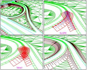
GRAD Module
 Commands from group GRAD are used for the
linear and conical slope design, modelling of curbs and sidewalks at
crossroads, modelling of ditches etc. Geometry of cut/fill slope is based on
these data: Commands from group GRAD are used for the
linear and conical slope design, modelling of curbs and sidewalks at
crossroads, modelling of ditches etc. Geometry of cut/fill slope is based on
these data:
-
the cross section of the slope
-
the string of POINTs through which
the slope is constructed (to the left or to the right)
-
the triangulated terrain surface in
relation to which the slope is calculated
This is why GRAD commands start with
three editors: slope editor, string editor and surface editor. The strings of
POINTs could be automatically generated along the edges of linear 3D models
constructed by using TMPL commands, but could be freely placed along the
pavement edges at crossroads, around the parking lots, around airport aprons
etc. At the crossroads, the strings could be automatically smoothed out in
vertical projection, providing the finest shapes of pavement morphology.
Along the crossroad strings, triangulated shoulder or sidewalk models are
constructed first, followed by the construction of cut/fill slopes.
All the features constructed by
using GRAD commands (cut/fill slopes, curbs, sidewalks, shoulders, ditches
etc.) are composed from the dynamically interlinked triangulated networks,
just as the linear 3D models created by using TMPL commands are.
Back to top
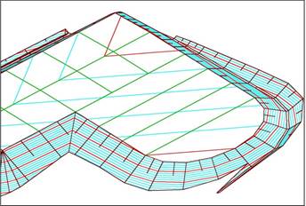
PTS, EDITRI and TUTIL modules
 PTS (PTS – Setting Points) – With
these commands, you can import surveyed data and manipulate break lines to be
fitted into the terrain model. You can also position points that will serve
as a base (or as a skeleton) for modeling planar facilities. PTS (PTS – Setting Points) – With
these commands, you can import surveyed data and manipulate break lines to be
fitted into the terrain model. You can also position points that will serve
as a base (or as a skeleton) for modeling planar facilities.
EDIT (EDIT – Editing Triangulated surfaces) – These commands support editing of triangulated surfaces, especially
manmade triangulated surfaces. The editing techniques include: intersections
of triangulated surfaces (usually cut/fill slopes), freehand widening of the
triangulated surfaces (such as the widening of the pavement approaching the
crossroad) etc.
UTIL (TUTIL – Triangulation Utilities) – With these commands, you can create some specific
triangulated surfaces, either simple ones, such as rows of paired triangles
representing the simplest of the building pads, or more complex, such as
lakes with the island openings.
Back to top
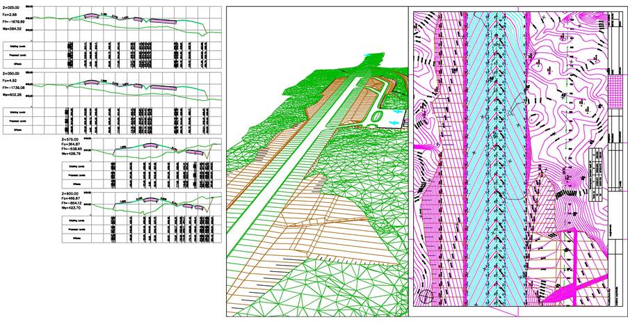
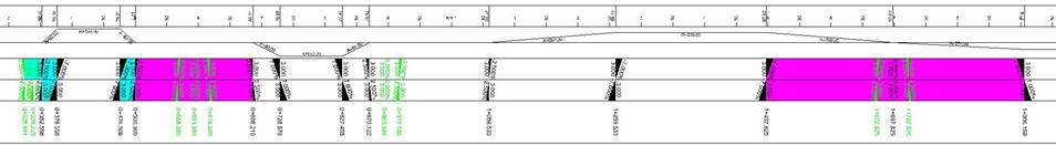
XSEC module
After completing the 3D model of a
linear facility, cross sections are extracted from the model. Series of cross
sections are literally cut out from the triangulated model. Extracted cross
sections are as much detailed as the 3D model is. Pavement layers, curbs,
drainage pipes and other elements of the roadway, if modelled, will be
included into extracted cross sections. Even nearby buildings, underground
structures, overpasses and other modelled facilities could be included into
cross sections. While arranging extracted cross sections, you can perform
multiple labeling and multiple volume calculations. That is to say, you can
label offsets and elevations for each layer within the pavement structure, calculate
their volumes as well as cut/fill volumes etc.
Back to top
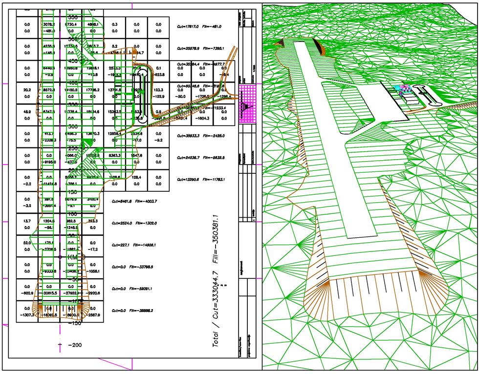
VOL module
 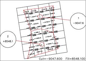 While the basic options for cut and fill calculations are
included in the labeling options of XSEC module, VOL commands primarily
support grid cell volume calculations, which are more appropriate for planar
facilities. There are also the tools for finding the centers of gravity (for
cut and fill masses), the tools for mass haul diagram construction, the tools
for the preliminary volume assessment from the longitudinal profiles etc. By
combining PTS, DTM and VOL commands, it is possible to contour the depth of
cut or fill, or the thickness of the pavement overlay and accurately
calculate quantities. While the basic options for cut and fill calculations are
included in the labeling options of XSEC module, VOL commands primarily
support grid cell volume calculations, which are more appropriate for planar
facilities. There are also the tools for finding the centers of gravity (for
cut and fill masses), the tools for mass haul diagram construction, the tools
for the preliminary volume assessment from the longitudinal profiles etc. By
combining PTS, DTM and VOL commands, it is possible to contour the depth of
cut or fill, or the thickness of the pavement overlay and accurately
calculate quantities.
Back to top
UTIL module
These commands support
layer manipulation, coordinate extraction and tabulating, rescaling labels
etc.
Back to top
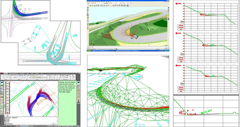
GCMDRIVE module
The module starts with the commands that
simulate movement of vehicles along the selected trajectories, providing
dynamics. It means that all the trajectories are dynamically linked to the
crossroads geometry, causing automatic repositioning of vehicles, while
manipulating a crossroad’s layout. Interactive techniques of puling and
pushing vehicles are introduced in GCM2009 (GCMx64).
Sight distance analyses are added to this
group as well. While the 3D based calculation of the available sight
distances was introduced in GCM2009, GCM++ introduces the analyses of the
stopping sight distances calculated from the anticipated speed levels.
Stopping sight distance requirements could be transferred into the cross
sections, thus supporting the obstacle removal.
Back to top
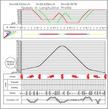
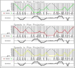
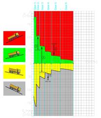
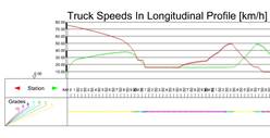
SPEED module
This module supports the speed
analyses for both passenger cars and heavy vehicles. The anticipated speed
levels for passenger cars are calculated from both the horizontal and the
vertical alignment of the road. Stopping sight distances, calculated from the
anticipated speed levels, are used by the GCMDRIVE commands for further
optical analyses of the road. Besides
the generation of speed diagrams, the travel time and fuel consumption data
are calculated for heavy vehicles.
Back to top
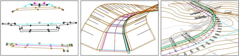
CSC1, CSC2 and CSCi modules
CSC1 (Cross
Sections Constructor 1) – Design approach introduced in
GCM2006, aims to produce highly detailed cross sections directly, avoiding
template definition. Simple pavement definitions (pavement blocks) are
attached to the key points along the centerline first. Based on these
pavement definitions, the cross grade and the width of the pavement are calculated
wherever the cross section is to be extracted. Thus, these rudimentary
pavement descriptions (pavement LINEs) are automatically imported into
“empty” cross sections (cross sections containing existing terrain only).
Finally, by using roadway details stored in “*.csc” files, detailed cross
sections are automatically constructed upon the pavement LINEs. All types of
two lane road and motorway details are supported: complex drainage details,
nonparallel pavement layers etc. Complex cut/fill slopes and filleted slopes
may also be used.
“*.csc” files are the files written in a
macro-language named CSC, whose syntax reflects the geometrical reasoning
underlying cross section drafting. The
file contains several sections: FU (Fill-Upper), FL (Fill-Lover), CU
(Cut-Upper) and CL (Cut-Lower). Each section defines specific detail to be
constructed upon the pavement edge - be it in Cut or on the Fill, be it Upper
or Lower edge of the pavement. In some cases, there must be also Edit
section, connecting the opposite edges of the pavement. When working with
motorway cross sections, there are also MU (Median-Upper) and ML
(Median-Lower) details.
CSC2 (CSC2 – Cross
Sections Constructor 2) – Just as the strings of POINTs are
used to mark important features (usually outer edges) of the 3D model,
Xstrings (XSTR) are used to identify some important positions within the
cross sections. Thus, for example, by using Xstrings, the ditches can be
inserted into the cross sections and manipulated vertically. Also, by using
Xstrings, cross sections can “communicate” with the 3D model by importing and
exporting strings into 3D. The entire CSC2 module is intended for Xstrings’
manipulation. Automated application of XSTR based commands, through batch processing
is introduced in GCM++. Construction of multiple cut/fill slopes, slopes’
filleting, topsoil removal, pavement widening, insertion of ditches and
retaining walls, all of it can be done in one pass, by deploying an
appropriate batch file.
CSCi (CSCi – Cross
Sections Constructor i) – This group supports the graphical
design of CSC details.
Back to top
XPAVE module
As the pavement blocks attached to the centerline determine the
pavement configuration in general, thus presenting the starting step in the whole
CSC process, XPAVE group automates the definition and attachment of these
blocks to the centerline. These commands create and manipulate “The
Superelevation Ruler” or superelevation scheme, the linear form containing
pavement-crossgrade/pavement-width definitions at each important point along
the centerline. Several methods of calculating cross grades are applicable,
including those based on the anticipated speed levels (or speed diagrams
generated by using SPEED commands). The content of “The Superelevation Ruler”
is automatically transferred into the pavement blocks and attached to the
centerline.
Back to top
GCMTAB module
A few commands exporting coordinates, cross sections’ data,
profiles’ data, quantities and volumes, all by using a new tabular format.
Back to top
PAVE module
For road resurfacing projects. Several methods of scraping and
leveling, optimizing vertical alignment, drafting resurfacing details within
cross sections.
Back to top
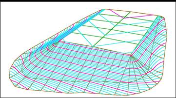
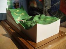
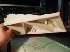
GavranSTL module
“GavranSTL” group, with its 4 toolbars, ORIENT, INQUIRE, CORRECT
and BUILD, supports the conversion of GCM models into STL (Stereolithography)
models, thus enabling 3D printing of GCM models. STL models are quite
demanding: there must be no holes, point triangles, needle triangles,
overlapping triangles and similar defects. The whole model must be created as
a “watertight” closed triangulated surface. Each of the triangle’s vertices
must be arrayed in counterclockwise direction, with the triangle’s outward
normal oriented in accordance with “The Right Hand Rule”. Roughly speaking, ORIENT commands deal with
the orientation ad reorientation of the triangles, INQUIRE commands examine
the model (mainly orientation of the triangles), while CORRECT group fixes
the defects on the model. The most interesting is the BUILD group that
transforms triangulated networks generated in GCM into the closed watertight
model. The final model resembles the solid shell of the sufficient thickness,
with the strategically positioned supports, providing structural strength and
saving the printing material at the same time.
Back to top
|